Formal Analysis Architecture
Blueprinting's product is hardware architecture exploration and simulation. Its core method is to formalize workloads, hardware blueprints, mappings, evidence, and constraints; derive progressively more concrete states; verify every semantic and resource obligation; and automatically analyze the resulting design space.
This section defines that formal-analysis architecture. The implementation borrows IR, lowering, pass, and verifier techniques from compiler engineering, but a compiler is neither a product plane nor a standalone system component.
From an architecture experiment to a simulation plan
An exploration experiment starts with:
workload suite
candidate ArchitectureBlueprints
mapping strategy space
deployment envelope
evidence snapshot and fidelity policy
objectives, constraints, seed, and budget
For each candidate, the system must produce a legal plan that satisfies the current stage's explicit completeness contract and can drive simulation and, when a target backend exists, program emission. Completeness must be defined by verifier coverage and target extensions rather than inferred from fields that merely look comprehensive. The core engineering problem is to remove unknowns in a controlled order without changing the workload truth between candidates.
Why formal derivation is the core method
Adjacent tools commonly maintain different representations for workload analysis, analytical estimation, network simulation, hardware simulation, and execution. Their formulas and overlap assumptions can drift, making a hardware comparison impossible to audit.
Blueprinting instead uses staged, monotonic derivation, implemented today with typed representations and verified transformation pipelines:
ModelIR                workload semantics
  -> DistributedTaskIR logical sharding and communication
  -> PortablePlanIR    architecture-independent mapping intent
  -> ConcretePlanIR    architecture-bound resources and execution plan
  -> MachineIR         optional target program representation
Each transition preserves upstream semantics, resolves a declared class of decisions, discharges explicit proof obligations, and creates an observable immutable checkpoint. This converts architecture comparison from a chain of unrelated formulas into one inspectable derivation.
Three analysis planes
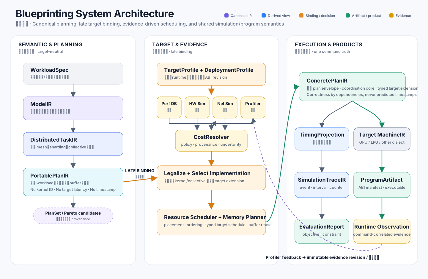
The formal-analysis architecture has three planes:
- the Semantic and Mapping Plane owns workload truth, distributed decomposition, exact work, and portable mapping alternatives;
- the Architecture and Evidence Plane owns candidate hardware resources, legality, deployment context, implementation choice, and cost evidence;
- the Simulation and Product Plane owns concrete commands, resource traces, reports, optional target programs, and observations.
Planes refer to each other through stable identities and digests. A performance provider cannot mutate workload facts; a target plugin cannot redefine frontend semantics; a simulation trace cannot become an independent schedule.
Architecture-binding boundary
Target-neutral work remains independent of any GPU, LPU, or experimental architecture through PortablePlanIR. A candidate ArchitectureBlueprint, deployment context, and evidence policy bind at the portable-to-concrete boundary.
Before that boundary, architecture requirements may prune impossible options, but vendor kernel IDs, physical engines, memory banks, routes, queues, and target latency are forbidden. After the boundary, the concrete plan owns selected implementations, placement, synchronization, buffers, and resource constraints. Cross-target coordination semantics enter the common core; target-only correctness semantics such as dataflow, routes, and issue slots require namespaced typed extensions rather than free-form metadata.
This is “late binding” from the workload's perspective. Hardware remains a first-class exploration variable: the system repeats the binding for many candidate blueprints rather than hiding one global target.
Shared concrete execution plan
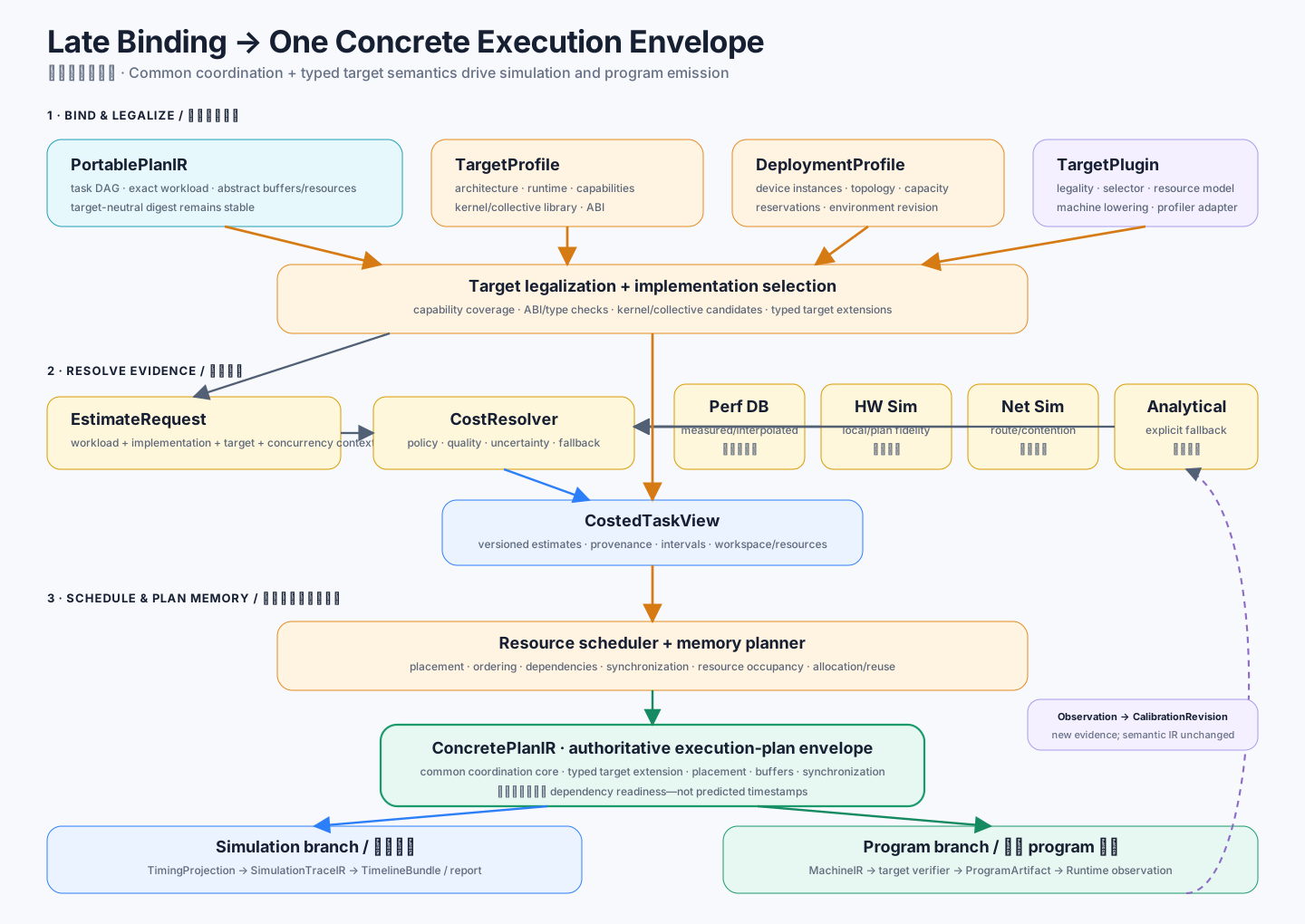
In the target architecture, the ConcretePlanIR envelope—the common coordination core plus typed target extensions—is the execution source shared by two products:
ConcretePlanIR + evidence
  -> TimingProjection
  -> SimulationTraceIR
  -> bottleneck / utilization / objective reports

ConcretePlanIR + target plugin
  -> MachineIR
  -> replayable or executable program artifact
Simulation is the primary exploration path. Program emission is optional and can arrive after hardware/ABI maturity. When both exist, they share command IDs, dependencies, queues, synchronization, and buffers, so measurements can validate the plan that was actually simulated.
The current v1 schema includes the common device/queue/buffer/command envelope, typed queue-order and slot/dataflow extensions, target verifiers, and two deterministic virtual reference binders. It still has no production target plugin, resource scheduler, occupancy model, or hardware-legality proof. It is therefore an experimental contract, not a frozen cross-target ABI.
Timeline as a staged product
Operationally, “compiling a timeline” means constructing a verified architecture-bound command plan, deriving predicted intervals and event traces under explicit evidence and simulator policy, and publishing those objects with provenance in a TimelineBundle.
ConcretePlanIR                 correctness and coordination
  + evidence / simulator
  -> TimingProjection          predicted time + uncertainty
  -> SimulationTraceIR         resource-correlated events
  -> TimelineBundle            analysis/replay product package
Predictive timestamps do not define readiness or buffer correctness. If an LPU or another target makes issue cycles or slots a program constraint, that constraint enters the concrete extension and MachineIR as a typed target semantic only after target binding. See the timeline staging path for the full boundary and acceptance gates.
Evidence is outside semantic IR
Exact operations, logical bytes, messages, dependencies, and abstract lifetimes belong to workload and planning IR. Throughput, latency, contention, energy, area, cost, and uncertainty belong to versioned evidence views.
This separation lets one candidate be reevaluated with analytical models, a performance database, hardware/network simulators, or measurements. Changing evidence can change ranking and a future schedule but cannot retroactively change workload semantics or a published experiment.
Planning, simulation, and calibration
| Stage | Responsibility | Product meaning |
|---|---|---|
| Exploration planning | Generate candidates, map work, legalize, estimate, place, schedule, and filter | Which blueprints are feasible and worth deeper evaluation? |
| Simulation | Execute the verified resource plan under declared models | How and why does each blueprint behave? |
| Calibration | Compare predicted and observed events, then publish evidence revisions | How should future experiments update target knowledge? |
Search may be expensive but must be bounded and reproducible. Runtime or simulation execution does not repeat an unbounded global optimization; a runtime may still retain backpressure, failure handling, and other bounded mechanism decisions explicitly allowed by its target contract.
Rejected shortcuts
The architecture rejects:
- one universal graph filled with optional target and timing fields;
- storing predicted duration as portable workload semantics;
- using a global overlap ratio instead of command/resource scheduling;
- fitting model/case-specific coefficients to a reference table;
- allowing each simulator or emitter to reconstruct its own schedule;
- binding one hardware target in the frontend;
- maintaining parallel legacy and new public IR hierarchies.
Each shortcut makes architecture candidates less comparable or conclusions less reproducible.
Current versus target system
The current connected path ends at PortablePlanIR, followed by an analytical SystemProfile estimate used for validation. Five typed representation schemas, verified transformation transactions, workload derivation, and the Calculon experiment are implemented foundations. Internal schema version numbers identify serialization contracts; they are not public compatibility promises until production producers, independent consumers, and migration policies exist.
First-class architecture blueprints, target/resource binding, concrete scheduling, event simulation, simulator providers, design-space search, and optional GPU/LPU program emission remain planned or contract-only. The status page is authoritative.
Reading the formal analysis foundations
- Derivation and verification model formalizes state, binding, proof obligations, automated analyses, and the concrete abstract machine.
- Timeline staging path separates command plans, predictive timelines, prescriptive timing, and LPU backend evolution.
- Golden derivation walkthrough follows one Transformer fragment through every representation.
- Analysis module architecture assigns Python ownership and extension boundaries.
- Floating-point numerical analysis defines the interactive numerical format analysis view and its boundary.
- Formal representation reference defines semantic contracts.
- Analysis and transformation reference defines verified transactions.
These internals serve the hardware exploration workflow described in Architecture Exploration and Models and Simulation. Unclosed cross-module architecture risks are tracked in the risk register; aspirational prose cannot substitute for an implementation gate.